Description
Background
The durability of concrete subjected to wetting and cycles of freezing and thawing can be enhanced by deliberately introducing many, small and closely spaced air bubbles (air voids) in the cement paste. During freezing, the ice formed in the capillary pores of the paste will expand into adjacent air voids without damaging the paste, provided the air-void spacing and the size distribution of the air voids are within certain limits. The spacing factor (maximum distance from any point in the cement paste to an air-void boundary) and the specific surface (ratio of the surface area of the air voids to their volume) are two parameters that can be used to characterize the air-void system. In general, a good quality, frost resistant concrete requires a spacing factor less than 0.20 mm and a specific surface greater than 25 mm-1.
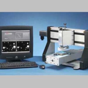
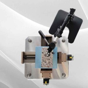
 The spacing factor and the specific surface of the air-void system are determined typically according to ASTM C457 “Test Method for Microscopical Determination of Parameters of the Air-Void System in Hardened Concrete,” or similar standards such as EN 480-11 “Admixtures for concrete, mortar and grout – Test methods – Part 11: Determination of air void characteristics in hardened concrete.” These methods require obtaining a sample from the hardened concrete on-site and preparing a properly polished specimen in the laboratory as illustrated in the photo to the left. The spacing factor and the specific surface are then determined manually by the linear traverse method using a microscope, or by an automated image analyses system. Determination of the air-void structure in this manner cannot produce timely information during construction, which would be needed to make adjustments to the concrete mixture if the measured parameters are not within specified limits.
Timely information is important, because practice has shown that the air-void structure created by air entraining agents can change easily during construction; for example, due to the type and dosage of normal or high-range water-reducing admixtures, by changes in sources of cementitious materials, by pressure influences during pumping of concrete, by high hydrostatic pressure, or by over vibration.
With the AVA, the air-void structure is measured after the concrete is placed but while it is still fresh, thereby providing timely information of the spacing factor and the specific surface of the airvoid system of the in-place concrete. The testing time is 25 minutes or less.
Principle
 The air bubbles entrained in a mortar sample, which is obtained from fresh concrete with a special sampling tool, escape into a blue AVA release liquid as the mortar is stirred. Provided the release liquid has the proper viscosity and hydrophilic character, the bubbles released from the mortar retain their original size and neither coalesce nor disintegrate into smaller bubbles.
Above the blue AVA release liquid there is a column of water through which the air bubbles rise. According to Stoke´s Law, larger bubbles will rise faster than smaller bubbles.
The air bubbles rising through the water column are collected under an inverted and submerged petri dish (buoyancy pan) attached to a sensitive balance. As air bubbles accumulate in the dishan, the apparent mass of the dish decreases as water is displaced by air. The apparent mass of the dish is recorded as a function of time.
Based on the recorded change in apparent mass of the pan, an algorithm calculates the size distribution of the collected air bubbles. From the size distribution, the spacing factor and the specific surface are calculated. The algorithm ensures the parameters are similar to obtained from ASTM C457 linear traverse measurements.
Correlation and Variability
The results from the AVA have been correlated to ASTM C457 and EN 480-11 determinations.
Among the published reports are:
- Brite Euram Project No: BE-3376-89, Task 2, “Quantitative and Qualitative Determination of the Air Void structure in Fresh Concrete,” Dansk Beton Teknik A/S, Hellerup, Denmark, Feb. 1994
- FHWA-SA-96-062, “Air Void Analyzer Evaluation,” Federal Highway Administration, Washington DC, USA, 1995
- Price, B., “Measuring Air Voids in Fresh Concrete,” CONCRETE, July/August 1996
- Wojakowski, J., “Air in Portland Cement Concrete Pavements,” Kansas Department of Transportation, USA, 2002
- Crawford, G.L., Wathne, L.G., and Mullarky, J.I.: “A ‘Fresh’ Perspective on Measuring Air in Concrete,” Federal Highway Administration, Washington DC, 2003 Bridge Conference, USA
- Kristensen, L.F.,”Kan man dokumentere, at der er 10 milliarder luftbobler i en m3 frisk beton?” Beton, Nov. 2012, pp.36-39
For example, the figures below compare air-void parameters obtained on fresh concrete samples using the AVA with the corresponding parameters obtained by microscopical analysis of the hardened concrete. ACI 201.2R, “Guide to Durable Concrete,” recommends that for resistance to freezing and thawing the spacing factor should not exceed 0.2 mm and specific surface should not be less the 25 mm-1. The plot on the left shows that for spacing factors below the critical value of 0.2 mm, the AVA values are on average slightly larger than from microscopical analysis, which is conservative. The plot on the right shows that for specific surface greater than the critical value of 25 mm-1, the AVA values are on average smaller, which is also conservative.


Reviews
There are no reviews yet.